
Robot Building Challenge
An Engineering and Physical Science Research Council Project
The Aims of the Program
- To encourage robot building in schools
- To introduce the basics of robot building to teachers
- To identify links between robot building and the National Curriculum in Science, Technology and Maths
- To encourage schools to enter their own robots in the Robot Challenge competition.
Description
Robot Challenge is based on the BBC's Robot Wars
Teams can be mixed by age and gender.
But it is best if they are only two in number.
The use of the Rover Kit in the design of the robots is mandatory in the first instance.
Starting Out
When starting out concentrate on building a robot, not a weapons system.
Skill in building and operating the robot are more important.
The aim of the competition is to out manoeuvre your opponent and push them out of the ring.
Rules can be developed to make the competition more exciting as expertise grows.
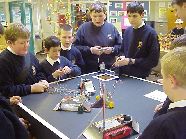
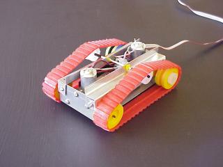
Mini Robot Challenge
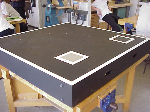
This entails building a small, remotely controlled vehicle based on the TEP "Rover Kit" and then having contests to see who can push an opponent out of the ring. No weapons are allowed, it is a test of skill in control and designing and building a superior robot. The TEP Rover kit is cheap enough for a class group to build several. Working in pairs, they can create ten different designs based on the simple criteria of manoeuvrability, speed, durability and control. A bench top sized ring made from half a sheet of MDF and you have the makings of a very exciting competition.
The "Rover Kit" lends it self well to the "try it" and see approach, because, with care, it can be assembled, tested, disassembled, modified, re-assembled and tested again several times. The very nature of the project fuels the desire to modify and re-build as you want to have another go after the first competition, in fact in can be very difficult to stop and move onto another project. By restricting everyone to the same basic components it is skill and ingenuity that are tested and not the depths of pockets.
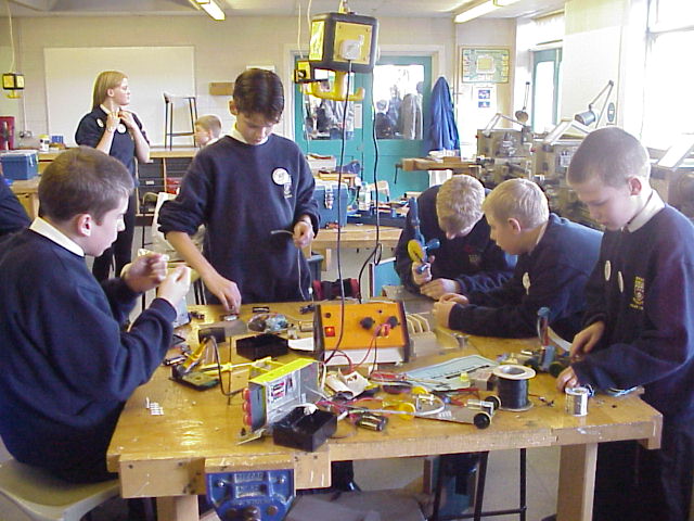
Project Organisation
The best advice is to start with a KISS, Keep It Small and Simple. Practice the basic craft skills on scrap material first, i.e. drilling holes in metal and getting holes to line up with the base plate on the motor gear boxes, cutting and filing sheet and round metal, bending and shaping sheet metal. Accuracy and finish are important. Once these basic skills are learnt, design work can move on a pace, with little for the teacher to do but offer advice and supply any extra materials if needed. The process quickly generates it own momentum and the skill is managing the speed of the project so that quality of outcome is maintained.
Resources
The basic "Rover Kit" comes with enough materials to make a working vehicle, but for the "Robot Challenge" you will need extra Aluminium Sheet (0.6mm thick) and access to basic metalworking tools and equipment. If you have a TEP Manufacturing Centre, so much the better as this contains most of the equipment you will need for the project. Jigs for drilling and marking out should be seriously considered as they improve the quality of the finished project, speed up the early stages of the manufacturing process and cut down on waste due to mistakes. You might also want to consider the use of vacuum forming to manufacture body shells, but this could be left to enhance the project later, if it is needed.
Resources for Mini-Robot Wars
Middlesex University Teaching Resources Ltd., Unit 10, The IO Centre, Lea Road, Waltham Cross, Herts, EN9 1AS
| Code No. | Description | Unit cost | No. | Cost | Invoice Total |
|---|---|---|---|---|---|
| TS6 002 | Aluminium Sheet | £1.11 | 1 | £1.11 | |
| TG1 110L | Left handed Clunk Click Gear Box | £1.99 | 1 | £1.99 | |
| TG1 110R | Right handed Clunk Click Gear Box | £1.99 | 1 | £1.99 | |
| EW2 030 | Motor Control Switch Board | £1.64 | 1 | £1.64 | |
| EC1 016A | Terminal Blocks 3 amp. | £0.26 | 1 | £0.26 | |
| EW1 012A | Ribbon Cable /mtr (enough for 10 robots) | £1.95 | 2 | £3.90 | |
| CP9 005 | Pultruded Rod | £1.09 | 1 | £1.09 | |
| £11.98 | |||||
| Or order the Magic of Engineering Micro Rover Kit | |||||
| MAG 003 | Magic of Engineering Micro Rover Kit | £10.92 | 1 | £10.92 | |
| MAG 003A | Class Pack of 10 Micro Rover Kits | £96.39 | 1 | £96.39 |
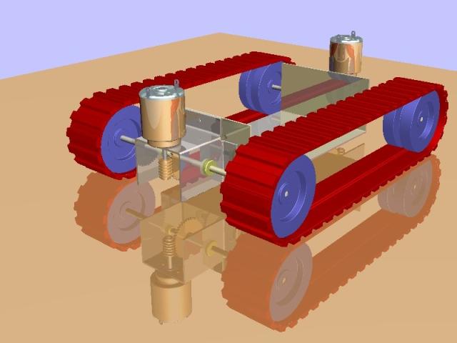
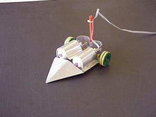
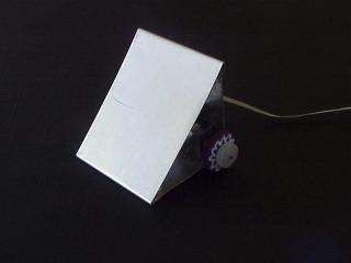
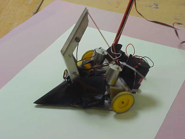
How to Build the basic body of a Mini-Robot
(Two Wheeled Version)
Introduction
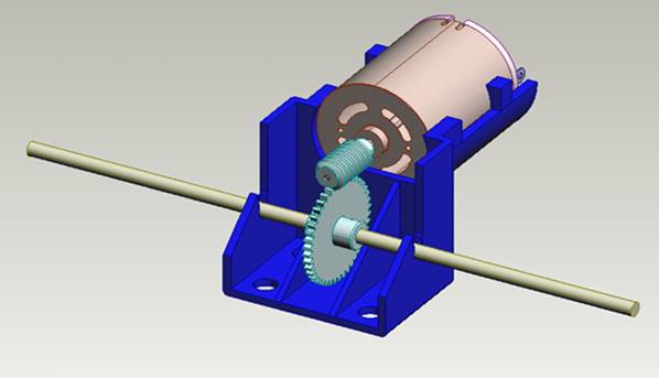
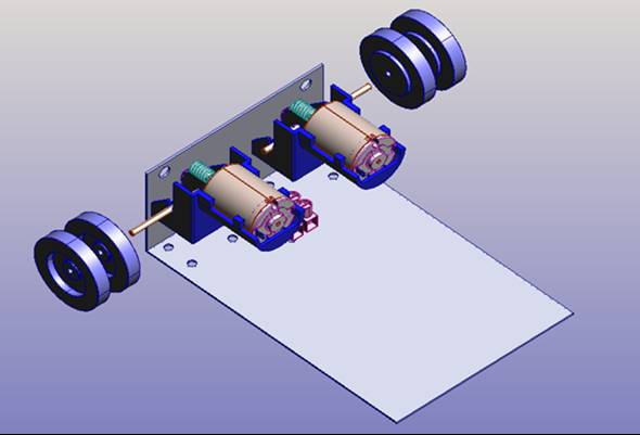
The gear boxes have to have one side of the axle longer than the other to allow them to be mounted side by side. The longer end may also need shortening to fit your design and this can be done on the rod cutting tool on the Manufacturing Centre.
The gear boxes are assembled after they have been bolted to the base plate as this make it easier.
Each gear box is held in place by four 12mm long nuts and bolts. Getting the holes exactly in line is difficult so it is best to strip the gear box down to it component parts making sure to put all the components in a safe place. The plastic gear boxes can then be fixed in place with double sided tape and then the holes can be drilled in the correct place in the aluminium through the holes in the gear box.
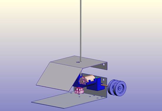
Construction Process
Start by marking out the Aluminium sheet to the sizes shown on the drawings. Lines are where the metal will be folded and only mark the centres of the holes. To mark the holes accurately for the gear boxes, strip the gear box and stick them to the base plate in the correct position with double sided tape and drill through the holes.
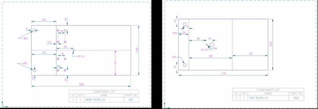
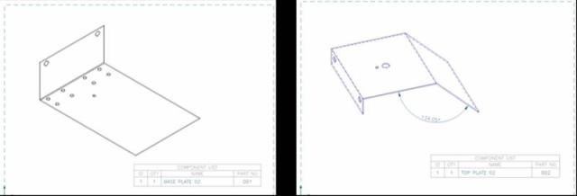
Bend the sheets to the angles shown
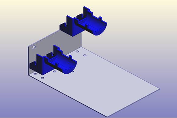
Bolt the striped motor gear box cases to the base plate
Cut the gear box axles to the required lengths
Reassemble the gear boxes with the long side of the axles to the outside
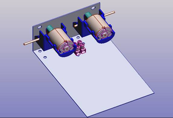
Carefully fit the wheels to the axles (two wheels to each axle)
Fit the connector block in the centre
Fit the top in place with two nuts and bolts
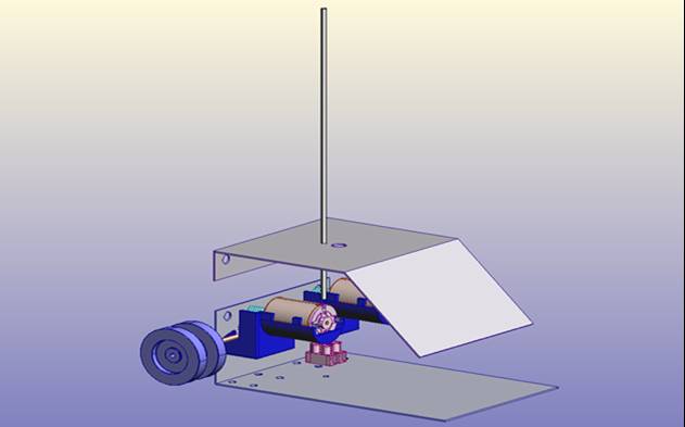
Pass the wiring harness through the large hole in the centre of the Top
Fit the aerial rod through the small hole
Fitting the Control Panel
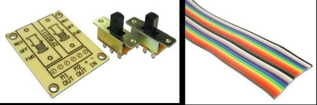
The control panel must now be assembled and fitted to the other end of the wiring harness. This must be done with very great care as the switches and the board can be easily damaged with overheating from the soldering iron.
Fit the two slider switches to the circuit board in the positions shown and solder the tabs underneath making sure a good contact is made with the circuit board.
If the control panel has not been supplied with a ribbon cable, strip off a two meter length of cable, six strands wide from a length of multicoloured cable. Separate and strip each end of the length and prepare them for soldering. Lay one end flat on the board, where it says M1 OUT, M2 OUT and + - IN, poke through the holes and solder (take careful note of which colour goes in which hole).
If you have not already done so, feed the other end of the cable through the hole in the top of the robot. Now solder the two strands connected to M1 to the right hand motor making sure that the strand connected to the right hand hole is connected to the positive (+) terminal of the motor. Do the same with the strands that are connected to M2 to the left hand motor.
Finally connect the last two strands to a battery snap using a connector block making sure that the strand connected to the hole marked + is connected to the red wire on the snap. Connect the snap to a battery box and check to see that when both switches are pushed forwards, both motors go in the same direction making the robot go forwards.
Trouble shooting the wiring
- If both motors run in the same direction but in reverse:
- Switch the leads of the battery snap round on the connector block.
- If one motor runs forward and the other reverse:
- Switch the leads round on the motor that is running in reverse
- If one or both of the motors does not run:
- Check the connections to the battery snap at the connector block
Check all your soldered joints and re-solder if necessary
Check the circuit board for short circuits
When you are satisfied that the robot is working correctly stick the battery box down to the robot, in a suitable place with double sided sticky pads and fit the top.To make sure that the wires are securely attached to the circuit board and wont get pulled out in use stick them down with tape or hot glue from a glue gun.
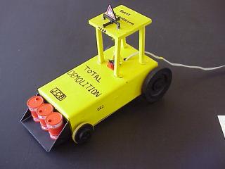
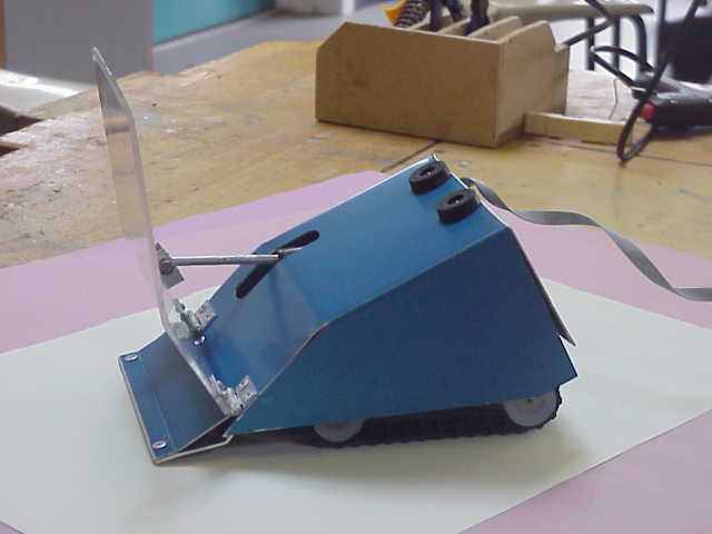
Your Mini-Robot wars Robot is now ready to fight!
The Rules of the Competition
Introduction
The competition is intended to create an interest in Technology and Engineering in young people through a FUN event.
The aim is to develop skills in making and controlling simple robotic type devices and to hone these skills through friendly competition.
It is not intended to create devices solely for the purpose of destroying other people's work.
Rules for Making
All Robots must be made from the basic TEP Rover Pack.
Additional materials may be used to add protection to the robots workings in the event of a crash or being pushed out of the ring.
No robot must be fitted with any device that is designed to damage a competitor's robot.
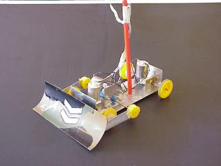
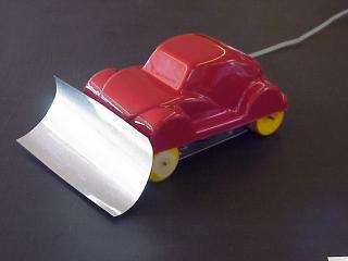
Devices that can be fitted are those solely designed to enable the robot to:
- assist with the pushing of another robot out of the ring
- turn an opponent over
- self-right a turned over robot
- Robots must be powered from dry cell batteries
- Robots must be controlled by an umbilical wire
Rules for Competing
- Robots will compete in a head on one to one knock-out bout
- A bout will last two and a half minutes
- A robot will be judged to have lost a bout if:
- It is pushed out of the ring by its opponent
- It drives itself out of the ring
- One of its wheels goes out of the ring
- It is immobilised for 30 seconds or at the end of the bout, which ever comes first.
- If both robots are still mobile at the end of a bout the judges will decide on a winner based on skill and aggression
- All decisions of the judges are final and will be made in the spirit of the competition as set out in the introduction